High-Efficiency POL Power Solution for Next-Generation AI Servers: RTQ2811A
Chang Lin, Jack Liu, Sophia Tong | AN094
As AI, cloud computing, and big data continue to drive higher computing density, server power designs are facing
increasingly stringent requirements for high efficiency, low noise, fast transient response, and high reliability.
Next-generation server SSDs and Point-of-Load (POL) applications not only require high-current, low-voltage power
delivery, but also demand high power density, a compact PCB footprint, and intelligent power management
capability.
Richtek’s RTQ2811A is specifically designed for next-generation server platforms. Featuring a high-efficiency synchronous buck
converter architecture with integrated I2C digital monitoring and flexible multiphase configuration, the& RTQ2811A improves power conversion efficiency, minimizes output ripple, and delivers fast transient response for
high-performance server and storage applications. This enables a highly stable and efficient POL power solution
for modern data center systems.
1. Server SSD and Point of Load Power Supply Design Challenges
As server SSDs and Point-of-Load (POL) applications continue to advance toward higher performance and greater
power density, power supply design is facing increasingly demanding challenges: Rapid load current transients
generated by high-performance processors, controllers, and memory devices require fast transient response,
accurate voltage regulation, and robust system stability. At the same time, higher system integration and tighter
PCB height constraints make thermal management and power delivery performance more difficult to balance.
1.1 Smart Power Trends: Higher Efficiency, Smart Monitoring, and Stability Requirements
Next-generation server power modules require intelligent control and real-time power monitoring to support rapid
current changes during high-speed operation. To handle fast load transients, the power supply must respond quickly
while maintaining stable output regulation across input voltage and load variations. High-efficiency conversion
reduces total server power loss and heat generation, while low output ripple helps improve signal integrity and
system stability in high-density server platforms.
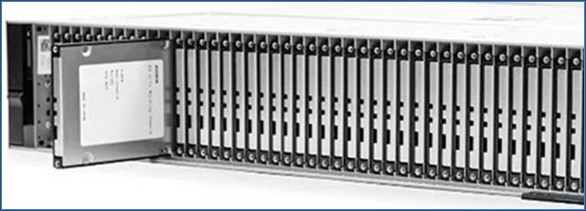
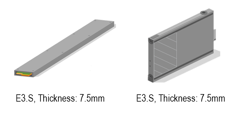
1.2 Size Constraints in Highly Integrated Designs
For high-density POL applications, such as EDSFF SSD modules, server backplane power modules, and storage
expansion cards, the power solution must balance compact size, thermal performance, and power delivery capability.
This is especially important when the available component height is limited, in some cases to less than 2 mm.
|
Server SSD Rack for E3.S
|
Component Thickness is Limited to 2mm
|
|
|
Enterprise and Datacenter Standard Form Factor
|
2. Control Topology Selection Based on System Requirements
To address the requirements for fast transient response, high power density, and high efficiency, Richtek
introduces the
RTQ2811A
multiphase buck controller for server SSD and POL power applications. The
RTQ2811A
incorporates a flexible control topology that allows designers to select Dual-Phase, Two-Channel, or Parallel
control by adjusting an external resistor. This flexibility enables the power design to be optimized for different
current levels, rail configurations, and system architectures.
Designed for space-constrained applications with strict power and thermal requirements, the
RTQ2811A
delivers high efficiency, fast transient response, low output ripple, and stable power delivery.
2.1 Dual-Phase Control
The dual-phase control operates two phases with 180° interleaving to reduce the inductor current ripple. This
provides the following benefits:
• Reduced Output Capacitor Requirements
• Fast Transient Response
• Balanced Current Sharing
• High Flexibility
2.1.1 Reduced Output Capacitor Requirements
The interleaved inductor current waveforms double the effective output ripple frequency relative to the switching
frequency, reducing output voltage ripple and input capacitor root mean square (RMS) current. This enables the use
of smaller or fewer output capacitors.
2.1.2 Fast Transient Response
Dual-phase interleaving compensates for current changes during sudden load steps, reducing output voltage droop
and recovery time while improving overall system stability.
2.1.3 Balanced Current Sharing
The output current is distributed between two phases, reducing current stress on each inductor and the high-side
and low-side MOSFETs. This helps reduce component temperature rise and improves long-term reliability.
2.1.4 High Flexibility
This topology is optimized for server SSD and POL applications requiring high current delivery and fast transient
response, while achieving an optimal tradeoff among power density, conversion efficiency, and system reliability.
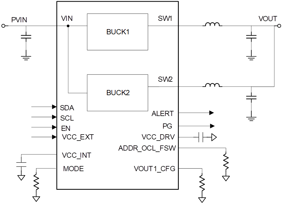
Figure 1. Dual-Phase Control
2.2 Two-Channel Control
The two-channel control provides two fully independent power outputs. Since interleaving control and current
sharing are not required, the control implementation is simplified and overall design complexity is reduced. This
topology is well suited for applications requiring multiple independent power rails with moderate current demand,
such as storage controllers, memory modules, and partitioned peripheral power systems.
Each output channel operates independently, without cross-channel interference, providing greater power
distribution flexibility and simplified system power management. Key features include:
• Simple Structure and Easy Implementation
• BOM Cost Advantage
• Flexible Power Sequencing
2.2.1 Simple Structure and Easy Implementation
Eliminating the requirement for interleaved timing control and current sharing simplifies circuit implementation
and reduces design validation complexity.
2.2.2 BOM Cost Advantage
The simple architecture reduces component requirements and lowers overall BOM cost.
2.2.3 Flexible Power Sequencing
Two-channel integration allows designers to configure rail timing based on system requirements, making the device
suitable for applications with defined power sequencing needs.
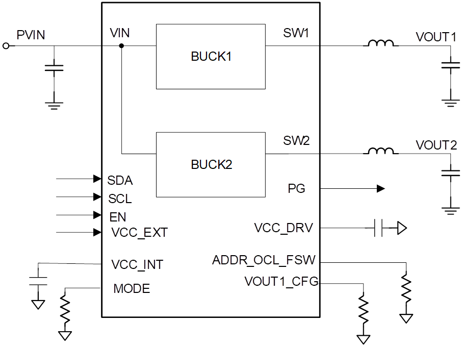
Figure 2. Two-Channel Control
2.3 Parallel Control
Compared to the dual-phase control, the parallel control simplifies hardware implementation and reduces overall
system cost. However, the lack of phase interleaving results in comparatively lower EMI and transient performance.
As a result, this architecture is typically adopted in cost-sensitive applications with moderate performance
requirements.
Key characteristics of parallel control architecture include:
• Fewer Inductors Required
• Simpler Control Method
• Lower Architecture Complexity
2.3.1 Fewer Inductors Required
Only a single inductor is required, which avoids the current imbalance that may occur when multiple inductors are
connected in parallel.
2.3.2 Simpler Control Method
A single-phase controller can be implemented with additional MOSFETs connected in parallel to distribute the
conduction current. This reduces the thermal stress on individual devices and helps simplify thermal management.
2.3.3 Lower Architecture Complexity
The simplified control reduces the complexity and helps streamline system design and debugging.
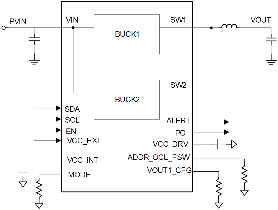
Figure 3. Parallel Control
Table
1. Comparison of Control Topologies
| Control Topology |
Dual-Phase |
Two-Channel |
Parallel |
| Key Advantage |
Provides high current through one control loop to optimize efficiency |
Provides two independent voltage outputs |
Increases the output current limit at a lower cost |
| Efficiency |
+++(highest) |
+(high) |
++(higher) |
| Load Transient |
+++(fastest) |
++(fast) |
++(fast) |
| Output Ripple |
+++(lowest) |
++(lower) |
+(low) |
| Switching Noise |
+++(lowest) |
++(lower) |
+(low) |
| Output Current Capability |
+++(best) |
+(good) |
++(better) |
| Cost Advantage |
+(good) |
++(better) |
+++(best) |
3. Advantages of the Design Scheme
3.1 High-Precision, Low-Noise Power Control Topology
For high-accuracy voltage regulation, the RTQ2811A uses the A
2
RCOT (Adaptive Asynchronous Ripple Constant-On-Time) voltage feedback control topology, together with a
high-precision reference and low-noise design, to maintain output voltage error within ±0.75%. Built-in
compensation and correction mechanisms reduce the impact of temperature drift and load variation on the output
voltage, supporting the accuracy requirements of server SSD and POL power rails.
The following sections provide detailed information on the temperature characteristics, load
regulation, and dynamic response capabilities. For more information regarding the A
2
RCOT voltage feedback control technology, refer to the product datasheet.
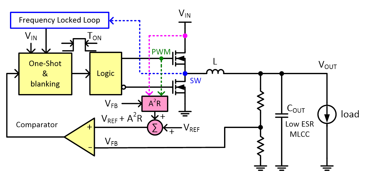
Figure 4. A
2
RCOT Control Loop
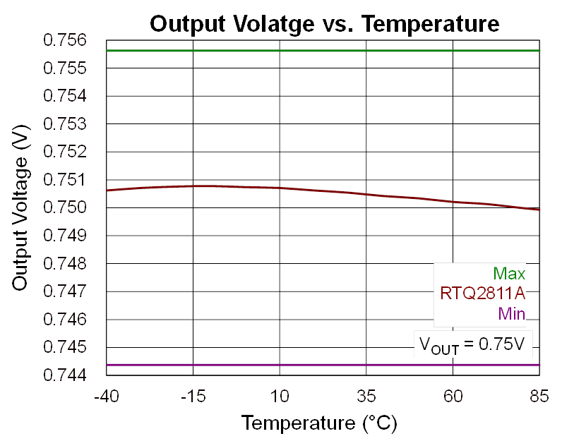
3.1.1 Excellent Temperature Compensation
Figure 5 and Figure 6 illustrate the RTQ2811A output voltage characteristics under different temperature conditions. For server SSD and POL
applications, voltage stability across temperature variation is critical, as these systems are typically required
to operate continuously under wide operating temperature ranges. Even minor voltage deviations may impact data
integrity and overall system reliability.
Across the operating temperature range from −40°C to 85°C, the RTQ2811A maintains a highly stable output voltage profile, with output deviation controlled within ±0.75%. The final
specification reference for the ±0.75% accuracy target should be confirmed based on product specifications,
customer requirements, or applicable server platform standards.
|
|

|
|
Figure
5. Output Voltage VOUT
= 0.75V versus Temperature Change
|
Figure
6. Output Voltage VOUT
= 2.5V versus Temperature Change
|
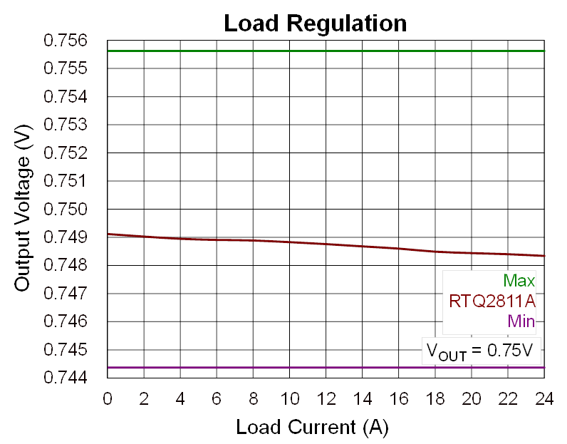
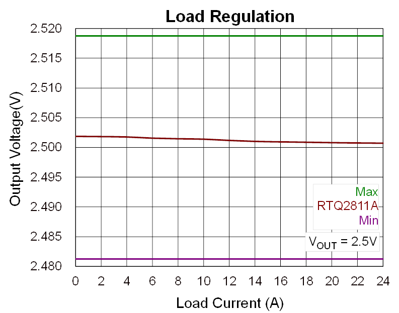
3.1.2 Accurate Output Voltage Regulation
Figure 7 and Figure 8 compare the
RTQ2811A
output voltage characteristics under different load conditions. In server SSD and POL applications, the power
solution must maintain accurate and stable output voltage during dynamic load changes. Excessive voltage variation
may cause data transmission errors, system instability, or reduced server performance.
With load conditions ranging from single-phase output up to 12A to dual-phase output up to 24A, the
RTQ2811A
maintains a smooth and stable output voltage profile, with deviation kept within the ±0.75% output accuracy
target.
|
|
|
|
Figure
7. Load and Output VOUT
= 0.75V Variation
|
Figure
8. Load and Output VOUT
= 2.5V Variation
|
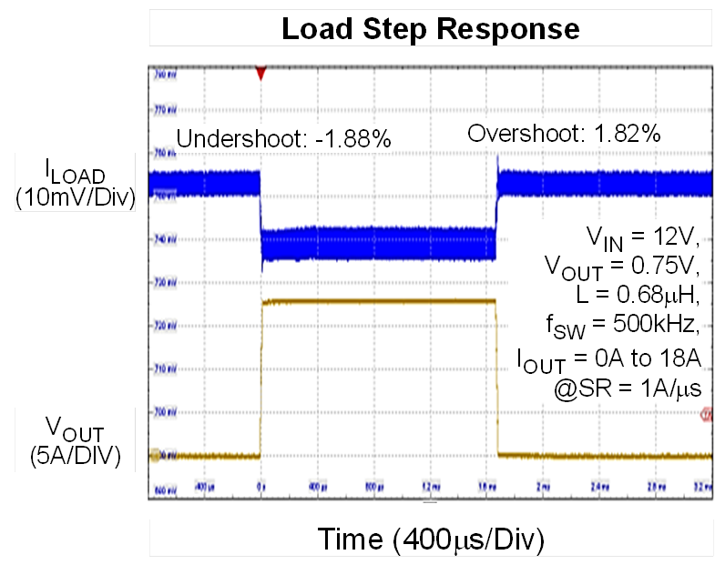
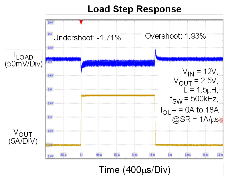
3.1.3 Fast Load Transient Response
The
RTQ2811A
incorporates advanced power control technology to provide stable power delivery during rapid load changes. Its
fast compensation loop detects and responds to load transients quickly, reducing output voltage droop and recovery
time. The device also includes output voltage overshoot suppression. When the system transitions to a light-load
or no-load condition, the control loop responds by turning off the low-side MOSFET to help limit output voltage
overshoot and prevent abnormal system operation.
|
|
|
|
Figure
9. Load Step Response at VOUT
= 0.75V
|
Figure 10. Load Step Response at VOUT
= 2.5 V
|
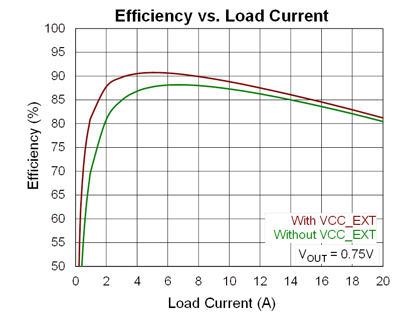
3.2 High Power Efficiency and Thermal Management3.1 High-Precision, Low-Noise Power Control Topology
In server SSD and POL applications, power efficiency directly impacts system power consumption, thermal
management, and overall operating cost. The RTQ2811A
utilizes high-efficiency synchronous rectification to achieve conversion efficiency exceeding 90%, reducing both
power loss and heat generation. Integrated ADC temperature monitoring and over-temperature protection further
ensure stable operation under high-load conditions, improving overall system reliability and component lifetime.
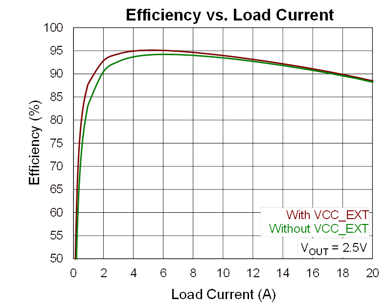
As shown in Figure 11 and Figure 12
, the RTQ2811A
achieves high efficiency through optimized circuit architecture and process technology. Improved efficiency
reduces server power dissipation, minimize thermal stress, and simplify thermal management design.
|
|
|
|
Figure
11. Efficiency Diagram at VOUT
= 0.75V
|
Figure
12. Efficiency Diagram at VOUT
= 2.5V
|
3.2.1 High-Temperature Warning and Reporting
Th RTQ2811A supports temperature reporting and allows the high-temperature warning threshold to be configured through I
2
C. The warning function can be set to activate from 100°C, helping the system detect thermal risk early and
maintain safe operation across different application environments.
3.2.2 Over-Temperature Protection
The RTQ2811A includes over-temperature protection with an I
2
C-configurable threshold. At the lowest setting, over-temperature protection is triggered when the temperature
exceeds 125°C. The device then shuts down all output rails and reports the fault through the ALERT signal. This
helps prevent thermal damage and enables real-time system health monitoring.
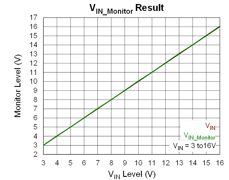
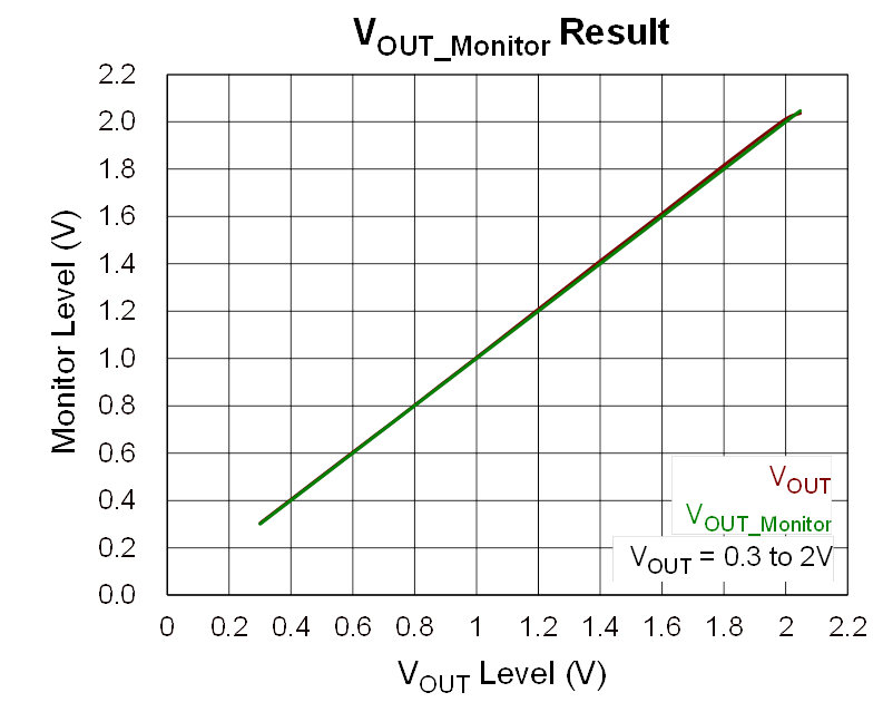
3.2.3 ADC Detection and Monitoring
The RTQ2811A integrates an ADC that measures external input voltage (V
IN
), output voltage (V
OUT
), output current (I
OUT
), and IC temperature. These values can be read through I
2
C. Continuous ADC sampling enables real-time monitoring of V
IN
, V
OUT
, I
OUT
, and IC temperature, allowing the system to track operating status and respond to abnormal conditions.
|
|
|
|
Figure
13. ADC Detection and Management of VIN
|
Figure
14. ADC Detection and Management of VOUT
|
4. Conclusion
The RTQ2811A is designed for data center server SSDs and POL power modules, integrating high efficiency, intelligent
monitoring, programmable control, and flexible architecture options to deliver stable and reliable power in
high-density, high-transient-load environments.
In addition to meeting the power requirements of current server and storage platforms, the RTQ2811A addresses the design challenges of next-generation high-performance computing and storage architectures. Its
flexible configuration and monitoring functions improve power design scalability and system reliability.
Richtek continues to strengthen its power management expertise by combining server platform experience with
ongoing product innovation, helping data centers improve system performance, power efficiency, and operational
stability.
To stay informed with more information about our products, please subscribe to our newsletter.