 |
|
How to make a DC/DC converter prototype in just a few hours |
| Newsletter Issue 25 | Jan. 25, 2018 |
 |
|
Parts selection and prototyping is an important part of the total design phase. A prototype can highlight design issues and provide insight in the overall performance of a selected part or circuit solution.
Richtek provides evaluation boards for checking the performance of parts. Our evaluation boards are optimized for good thermal and overall circuit performance. But your final circuit may be different from our evaluation board: For example, you may have different board layout, or have a slightly different application circuit. In most cases, you’ll make a CAD layout of your total application, and do a full board prototype run, which probably will take several weeks.
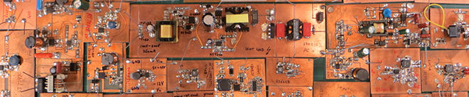
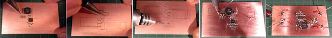
But did you know you can make a quick hand-made prototype for most DC/DC converters with leaded packages in only a few hours? The method is called isolation routing. Basically you take a double layer bare copper PCB, and use a fine engraving tool to cut slots in the copper to form separate copper islands. Then you can connect the components between the copper islands. It works quite well for DC/DC converters, because the copper islands have low inductance and resistance, and the bottom copper layer can be used as a good low impedance ground plane. Vias can be added by simply drilling a hole in the PCB and soldering a wire from top to bottom. With some practice, such a board can be finished in one or two hours.
|
 |
|
What tools do need? |
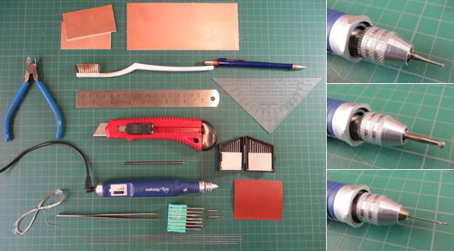 |
- A high speed drill (like engraving tools with adjustable drill chuck) that can fit different size drills and cutting tools
- Fine tipped cutting bits, (like the ones used for dental work), or fine diamond burr bits
- 0.5/0.6/0.7/0.8/0.9/1mm drill bits
- Fine sanding paper (grit 500)
- Brush for cleaning
- Fine pencil 0.5mm & eraser
- Sharp knife & metal ruler
- Fine tip tweezers
- Sharp centering punch or a steel pin with a sharp tip
- Double layer bare copper PCB material, 1.6mm thickness epoxy glass composite, available at most electronics shops
- 0.6mm and 0.9mm “jumper wire” for making vias
- Fine-tipped soldering iron; a hot air soldering station
|
|
How to select parts and design the circuit?
|
|
|
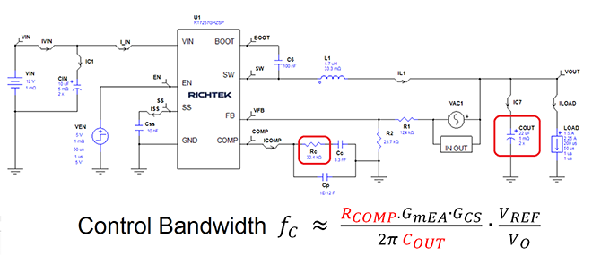
You can use Richtek Designer to help you find suitable DC/DC converter parts, and produce a full schematic suitable component values. But please note that the simulation is only accurate when you enter the values of the actual key components that you’re going to use. This is especially important for the MLCC output capacitor value, which needs to be checked via vendor datasheets to know its value in the actual circuit operation conditions.
|
|
How to make the layout?
|
|
|
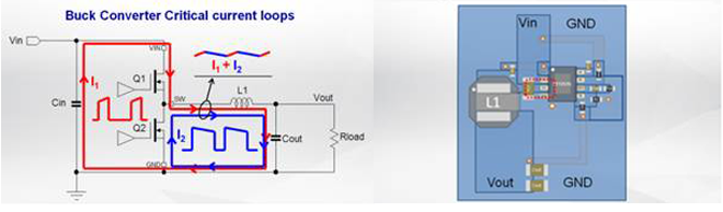
When making layouts for DC/DC converters, you need to consider the critical current loops of the converter and make the layout in such a way that critical loops are minimized. In a buck converter, the input loop is critical because the currents in the input loop are discontinuous and can generate a lot of EMI. But in a boost converter it is just opposite: the output loop is most critical.
You should also check which nodes have fast switching voltages and keep these nodes away from sensitive circuits. In a good layout, the high switching current section and small signal section should be separated. Try to ground small signal sections via a clean route to the IC ground.
|
|
How to check thermal conditions? |
|
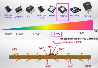
Most SMD packages are cooled by the PCB copper. Knowing your part’s power dissipation is very important to estimate whether it will be OK or not in your final application. Different SMD IC packages have different power dissipation capabilities and the PC board size, layout, number of layers, other nearby hot components, PCB ambient temperature and airflow will also determine whether a power device will be OK or become too hot in the application.
|
|
|
Getting Started |
|
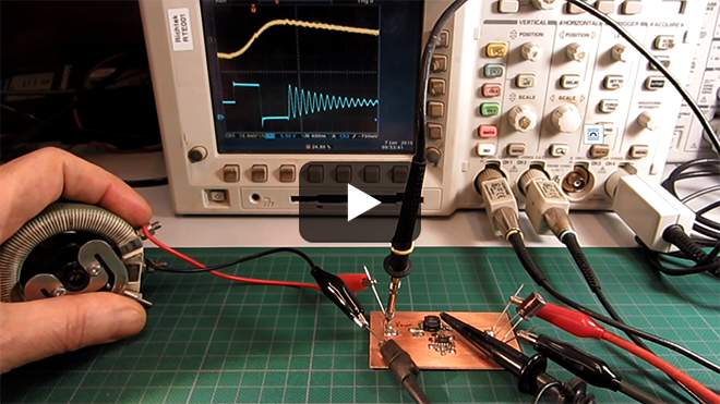
Would you like to see an example of how you can design, build and test a complete DC/DC converter prototype?
Please watch the video:“ How to make a DC/DC converter prototype in a few hours’’
The video shows how to make the component selections, optimize the schematic, design the layout and build the board. Furthermore it shows how to make output ripple measurements, stability measurements and thermal measurements. A few examples are given how a poor layout can affect performance.
|
|

|
Follow Us on Facebook!
We are delighted to announce the new Richtek Europe company page.
Our goal with this new company page is to provide an easier way for you to receive weekly updates and insights about technical articles, design tips, company news, and more. Please stay tuned with us!

|
|
|
|
NEW PRODUCTS |
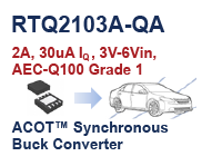 |
RTQ2103A-QA is an automotive AEC-Q100 grade 1 qualified, 2A, 3V-6Vin, 0.45V-5.5Vout, 30μA Iq ACOT Synchronous Buck Converter in a SOP-8 package. Operating from -40°C to 125°C, RTQ2103A provides up to 2.7MHz operation frequency to minimise external component size and avoid AM radio band interference. The ACOT topology allows transient response to be optimised over a wide range of loads. It is ideal for automotive infotainment, automotive instrument clusters & HUD, car connectivity, etc.
Get Free RTQ2103A-QA Sample Now
|
 |
RT6218A/B (PSM/PWM) is a 2A Iout, 4.5V-18Vin, 0.765V-6.5Vout, 650kHz, ACOT Synchronous Buck Converter in a small TSOT-23-8 package. Featuring programmable soft-start and Power Good, it is suitable for STB, LCD TVs, home networking devices, etc.
Get Free RT6218A/B Sample Now
|
 |
RT6276
RT6278
RT6280 is 6A/8A/10A Iout, 4.5V-23Vin, 500kHz ACOT Synchronous Step-Down Converter family in an UQFN-12HL 3x3(FC) package. It is ideal for industrial and commercial low power systems, networking communication, computer peripherals, etc.
See Evaluation Board:
RT6276
RT6278B
See other ACOT Buck converters
|
| |
|
|